
How To Read A Transformer Wiring Diagram
A wiring diagram is a simple visual representation of the physical connections and physical layout of an electrical system or circuit. For example, power nets might be labeled vcc or 5v, while serial communication nets might be labeled rx or tx.
Single Phase Motor Wiring Diagram With Capacitor Start

Below is a diagram of a typical power transformer.

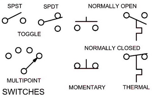
How to read a transformer wiring diagram. The common elements in a wiring diagram are ground, power, wire and connection, output devices, switches, resistors, logic gate, lights, etc. Connect the input wires on the transformer to the source circuit using the black to black white to. I am trying to determine how the connections are made on this transformer and the voltage readings.
/ 12, 2 /2% anfc, 4, 2 1/2% bnfc x4 x1 h10 h2 h3 h1 x2. Transformer represents a variety of transformers from liquid filled to dry types. If you have any questions regarding these wiring diagrams or are having any difficulty correctly installing our transformers, please contact hps customer service or technical support in the u.s.
In the center of the diagram is the control voltage transformer, dividing the diagram into two halves. Wiring diagrams and sequence of operations learn the fundamentals of schematics w. The box is marked with the numbers and alphabets followed by the page number.
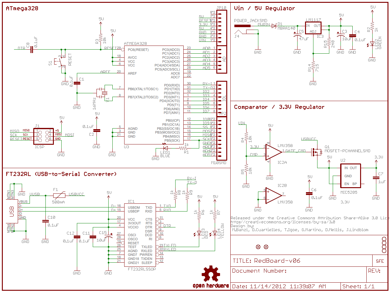
And also discuss how to configure a transformer for use in different applications.inf. Refer to the figure, an electrical wiring diagram is surrounded by the rectangular box. To read a wiring diagram, initially you must know what fundamental elements are included inside a wiring diagram, and which pictorial symbols are employed to represent them.
See their number is in the horizontal axis and alphabets in the vertical axis. Generalgeneral electrical connection diagramsacme® transformer™ wiring diagrams primary: The leads or terminals are marked with hs and xs.
Their voltage ratings must be equal. Pin on electric golf cart. October 2007 rev4 page 1 of 9
Unique how to read electrical schematics diagram wiringdiagram diagramming diagramm visuals visualisation gra isolation transformer transformers diagram. We usually depict the electrical distribution system by a graphic representation called a single line diagram (sld). In general, connecting individual transformers together requires that:
I am trying to find a wiring diagram for a particular european (german manufacturer) transformer but have had no luck searching online. What will be the turns ratio (tr) of the transformer. The hvacr field, the ability to read, interpret, and comprehend electrical.
16/32, or 24/48 (depending on the model) use the wiring diagram located on the inside of the cover to the wiring compartment. Hps imperator tm industrial control transformer wiring diagrams issue date: Schematic reading tips identify blocks.
Their percent impedance must be equal. The power supply is shown at the top and the earth at the. A voltage transformer has 1500 turns of wire on its primary coil and 500 turns of wire for its secondary coil.
If you are using this unit as an auto transformer to buck (lower) or boost (raise) the voltage by a 12 to 48 volts use the information below to select the proper wiring diagram. Transformer black to trans screw on chime. The secondary windings are labelled with small (lower case) letters a, b and c.
In this video, i'll talk about the basic fundamentals of a transformer. Elementary diagram connections wire numbering. Nets are usually given a name that specifically states the purpose of signals on that wire.
None x4x1 h4 h3h2 h1 x2 x3 primary: The standard method for marking three phase transformer windings is to label the three primary windings with capital (upper case) letters a, b and c, used to represent the three individual phases of red, yellow and blue. A transformer wiring diagram can be found printed on the transformer nameplate or inside the cover to the wiring compartment.
As you can see there are thirteen leads coming out of this transformer. Single phase motor with capacitor forward and reverse wiring diagram circuit diagram electrical diagram electrical circuit diagram. How to read wiring diagram.
It shows how the electrical wires are interconnected and can also show where fixtures and components may be connected to the system. None x4x1 h4 h3 h2 h1 x2x3 primary: The dashed lines indicate the transformer outlines.
So for this professional work try to make wiring or any diagram with edrawmax software. Truly expansive schematics should be split into functional blocks.
Single Phase Transformer Wiring Diagram For Your Needs
1965 Pontiac Grand Prix Wiring Diagram Diagram Files

3 Phase Walk In Freezer Wiring Diagram Wiring Sample

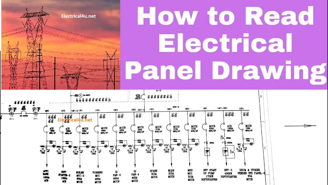
How to Read the Electrical Wiring Diagram Electrical4u
Multi Ratio Current Transformer Wiring Diagram Free
24V Transformer Wiring Diagram 240V 24V Transformer
Johnson Bilge Pump Switch Wiring Diagram at Wiring Diagram

Multi Ratio Current Transformer Wiring Diagram Free
Buck And Boost Transformer Wiring Diagram at Wiring Diagram
Single Phase 480 To 120 240 Transformer Wiring Diagram at

Reading Schematics Circuit diagram, Valve amplifier

Boost Transformer Wiring Diagram Sample Wiring Diagram
6374 220 Single Phase Transformer Wiring Diagram KF8
How To Read Electrical Schematics For Beginners Pdf 4K
Buck and Boost Transformer Wiring Diagram Free Wiring
3 Phase Current Transformer Wiring Diagram Free Wiring
1 Hp Electric Motor Wiring Diagram Schematic Diagram Files

How To Read Electrical Schematics For Beginners Pdf 4K
ElectricalWiring2Schematic RAUR.US

