
Fan Regulator Wiring Diagram
I am rewiring a table fan speed control switch. You have just read the article entitled regulator kipas siling.
Hampton Bay 3 Speed Ceiling Fan Switch Wiring Diagram Download

Eurowind electronic regulator for ceiling fan youtube.

Fan regulator wiring diagram. Construction and working the power supply phase line is connected with one terminal of fan and other terminal from fan is connected with regulator circuit here triac connected across the fan and neutral power line the gate terminal is connected with diac the capacitor 2a104j is an polymer capacitor. Triac is a semiconductor device belonging to the family of thyristors. It is used to control the speed of a ceiling fan.
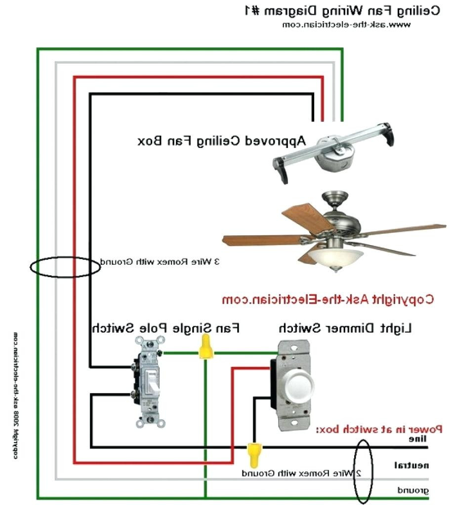
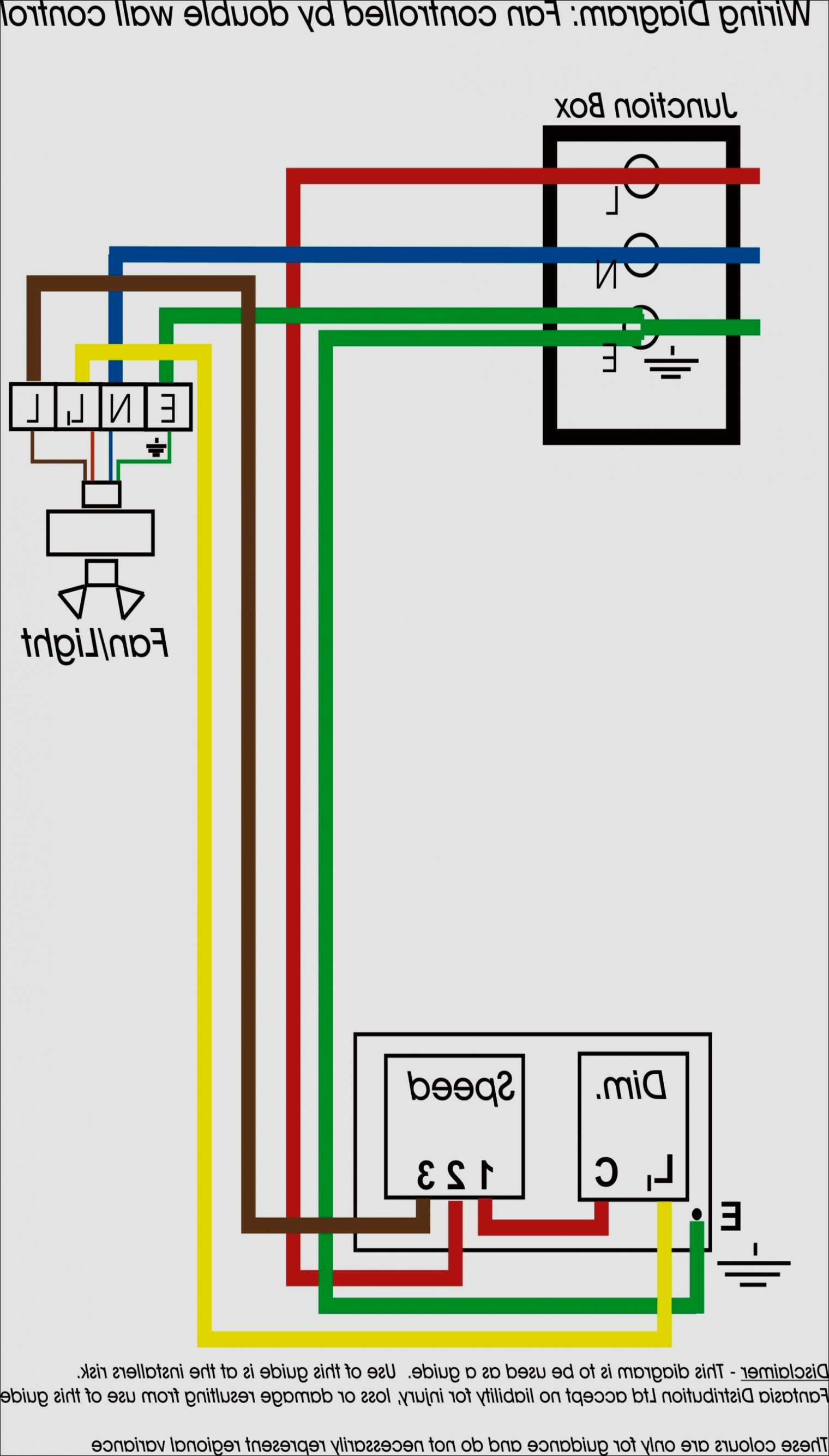
Ceiling fan with light kit wiring diagram this wiring diagram illustrates the connections for a ceiling fan and light with two switches, a speed controller for the fan and a dimmer for the lights. 1 trick that we 2 to printing a similar wiring plan off twice. By admin · published october 16, 2020 · updated october 30, 2020.
Today we are going to know the proper ceiling fan connection here you will know the connection of ceiling fan with a ceiling fan capacitor electronics basics. This is 220v ac dimmer circuit diagram based on capacitor, in the capacitive dimmer/regulator no noise.resistor, one capacitor, one diac and one triac. Simple electronic fan regulator circuit pcb schematic circuit electronics circuit diagram.
A single fan and light control using an individual switch is a very commonly used wiring circuit in house, offices, etc. Wiring diagrams are provided with all fans. These guidelines will be easy to understand and apply.
2 years ago reply upvote. New 1 box 3 sets hipson hp 5600 ceiling fan fans 56 5 speed regulator kipas. How i connect a ceiling fan without regulator quora.
Ceiling fan regulator wiring diagram from www.electrical101.com print the wiring diagram off plus use highlighters to trace the signal. Connect another terminal of the switch to any one terminal of the fan regulator. You can also bookmark this page with the url :
The switch provides the function to on or off the fan whereas the fan regulator provides the function of speed control. Table fan wiring diagram with capacitor pdf. Fan regulator wiring diagram youtube.
The needs for external wiring and the hand fabricated bracket for the transpo voltage. Wiring diagrams october 21, 2021 08:07. The circuit mainly based on z0607 triac.
Most 1 wire alternators have a charging point set around 1200rpm or higher. Which wire is coming from the running. The fan regulator is connected between the fan and the switch.
This ceiling fan regulator circuit built with few numbers of parts. Categories wiring diagram tags connection. In the circuit, the phase line is connected parallel to the one pole of the two spst switches and the neutral line is connected parallel to.
Fan connection with regulator fan regulator wiring diagram electrical wi light switch wiring connection regulators. Take a zero board or printed circuit board pcb and connect the circuit as given in the below. Fan regulator is a device by which we can control the speed of rotation of the fan.
Quora ac calculating the capacitor values to control ceiling fan speed how. It is intended to assist all the average consumer in creating a correct system. A fan regulator circuit which can also be used as a simple lamp dimmer circuit this fan speed regu simple lamp.
The source is at the switches and the input of each is. Also, shown the internal connection of running coil/winding, starting coil/winding and capacitor. In the other words it is an ac motor speed controller circuit, as because it's control the speed of a ac motor (ceiling fan).
Wiring diagram will come with a number of easy to stick to wiring diagram guidelines. In this post, we have explained the ceiling fan wiring diagram.in a ceiling fan, you should know which wire is the common wire from the motor of the ceiling fan. Wiring diagram of ceiling fan with regulator.
Harbor breeze ceiling fan wiring diagram collections of harbor breeze ceiling fan wiring diagram collection. Considering maddening to remove, replace or fix the wiring in an automobile,. Ac calculating the capacitor values to control ceiling fan speed ac calculating the capacitor values to control ceiling fan speed fan regulator circuit, ac lamp dimmer, ceiling fan electronic regulator how does a fan speed regulator work?
2 two way switch 1 fan regulator ceiling fan wiring l duration. Fan regulator connection diagram and internal circuit explanation electrical circuit diagram electrical diagram electrical wiring diagram. Harbor breeze ceiling fan light kit elegant 3 speed ceiling fan pull.
If we tend to increase the worth of resistance the free fall across the electrical device is redoubled that the voltage across the fan motor is faded and ultimately the speed. Fan wiring diagram with regulator. In this article, i will show you the complete ceiling fan wiring, ceiling fan connection is a very easy task, a condition that you should know about the color code of ceiling fan wiring.
Also, follow the below procedure. If you want to connect a fan regulator also, then the above diagram will help you. The problem essentially is that all car is different.
In the triac based electronic ac dimmer fan regulator circuit there are mainly three components used. The simplest approach to read a home wiring diagram is to begin at the source or the major power supply. Used the files section to install the transpo voltage regulator after deeming man that is quite a lot of work and requires running the wiring.
Fuses must be able to carry starting loads Table fan connection diagram pdf. Here we have used a 230v electronic fan regulator to control the speed of the fan.
Connect the phase terminal of the power supply to the anyone terminal of the spst switch. In the above schematic wiring diagram of a celling fan shows the very simple and easy external connection that connection of celling fan, fan speed regulator, on/off switch with single phase power supply at home. In this ceiling fan regulator circuit r1500kw is a variable resistor that is used to adjust the fan speed.
When you make use of your finger or perhaps the actual circuit with your eyes, it is easy to mistrace the circuit. Protection fuses in the circuit should be regarded as protecting the wiring only against short circuit, they are not suitable for overload protection. This is a simple ceiling fan regulator circuit diagram tutorial.
Ceiling fan and light wiring circuit diagram.
Leviton Sureslide Dimmer Wiring Diagram

How To Connect Fan Regulator With Two Way Switch Cbb61

Ceiling Fan 3 Speed Wiring Diagram Database Wiring

Table Fan Diagram ALL

Hampton Bay Ceiling Fan Switch Wiring Diagram Wiring Diagram
Get Hunter Fan Wiring Diagram Download

Ceiling Fan 3 Way Switch Wiring Diagram Download
Hunter Ceiling Fan Speed Switch Wiring Diagram Hunter

Hunter Ceiling Fan Capacitor Wiring Diagram Download

How to Wire a Ceiling Fan? Dimmer Switch and Remote

Hampton Bay 3 Speed Ceiling Fan Switch Wiring Diagram
Harbor Breeze Ceiling Fan With Remote Wiring Diagram

Exhaust Fan thermostat Wiring Diagram Collection

Ceiling Fan Light Wiring Instructions

The World Through Electricity How to wire a ceiling fan

Hunter 3 Speed Fan Control and Light Dimmer Wiring Diagram

Hampton Bay 3 Speed Ceiling Fan Switch Wiring Diagram
Hunter Ceiling Fan Capacitor Wiring Diagram Download

Fan Regulator Wiring Diagram YouTube

